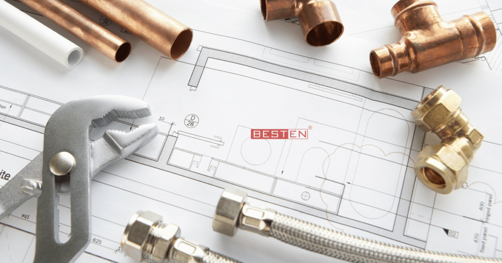
An isometric drawing is a detailed orthographic drawing that represents the details of the 3D structure of the Industrial piping system in a 2D format. It is the most important deliverable of the piping engineering department. Also, it is a standard practice for Industrial Infrastructure designers to create isometric drawings for piping systems to present all details in –depth.
The isometric drawing for piping consists of three sections. So, now let us see the main Graphic section. It consists of Isometric Representation of a pipeline route in 3D space, which includes the following information :
- Line number.
- Flow Direction.
- Support Tags and location.
- Piping Components location.
- Weld Locations.
The Value Isometric Drawings for Piping Design:
Isometric is one of the essential parts of the overall piping design for industrial infrastructure design projects. Also, Isometric drawings are extensive documents that hold valuable info used by different project stakeholders at different times.
Kind Of Data Typically Conveyed In Piping for Isometric Drawings
- Isometric drawings for piping design portray a graphical representation of the 3 Dimensional piping system.
- Also, this shows the straight lengths of all the pipe runs on the Isometric drawing as precise as required.
- Thus, this indicates the line numbers for pipe runs within the Isometric drawing.
- Moreover, the line numbers indicate the fluid service, piping class, and material, insulation details, etc.
- Rest other components, such as flanges, valves, elbows, and other fittings, need to be drawn.
- It also includes a table that lists the numbers and descriptions of each type of fittings represented in the drawings.
- If the piping system is complicated, then each pipe runs are represented on the separate isometric diagram.
Industrial Infrastructure Design Project :Specific Instructions for Isometrics Checking
Every project has specific requirements. Also, these need to be reflected in isometrics drawings. Some of these requirements can be regarding following points
- Pressure Safety Valves
- Inlet/outlet bolt scope of supply.
- Outlet bolts and gaskets in which line, inlet, or outlet.
- Fire Fighting lines
- Spool piece requirements.
- Flange types (flat face or raised face)
- Process Vents and Drains
- Hydrotest vents and drains
- Flow meters straight run requirements
- Insulation thickness and scope
- Valves selection / Tagging
- Jackscrew flange requirements
- Hold identification
- Union / Coupling requirements
- Galvanized lines spool sizes
- Dyke Penetration markup
- Support markup notes
- Orifice flange orientation / typical sketch
- PID Tapping sequence markup
- Flange/gaskets and bolts at iso sheet end
- Sheet break philosophy.
Therefore, it will be a best option to consult Industrial MEP consultants, to get isometric drawings for your industrial piping design.


